What is a Coil Inductor and How Does it Work?
A coil inductor is a crucial component in electrical circuits, often found in power supplies and communication systems. It stores energy in a magnetic field when electrical current flows through it. This principle is simple yet powerful. However, many users overlook its importance and functionality.
Understanding how a coil inductor operates is essential for engineers and hobbyists alike. It uses coils of wire to create inductance, which resists changes in current. This can lead to misconceptions about its role in circuit design. Furthermore, the quality of the coil inductor can greatly affect the performance of the entire system.
Some coil inductors are prone to overheating or saturation if not properly designed. These failures can lead to circuit inefficiency. Moreover, the choice of core material and winding techniques is often underestimated. This can result in unexpected challenges when working on projects. Recognizing these factors can enhance overall reliability and performance. Understanding the nuances of coil inductors makes users more proficient in their applications.
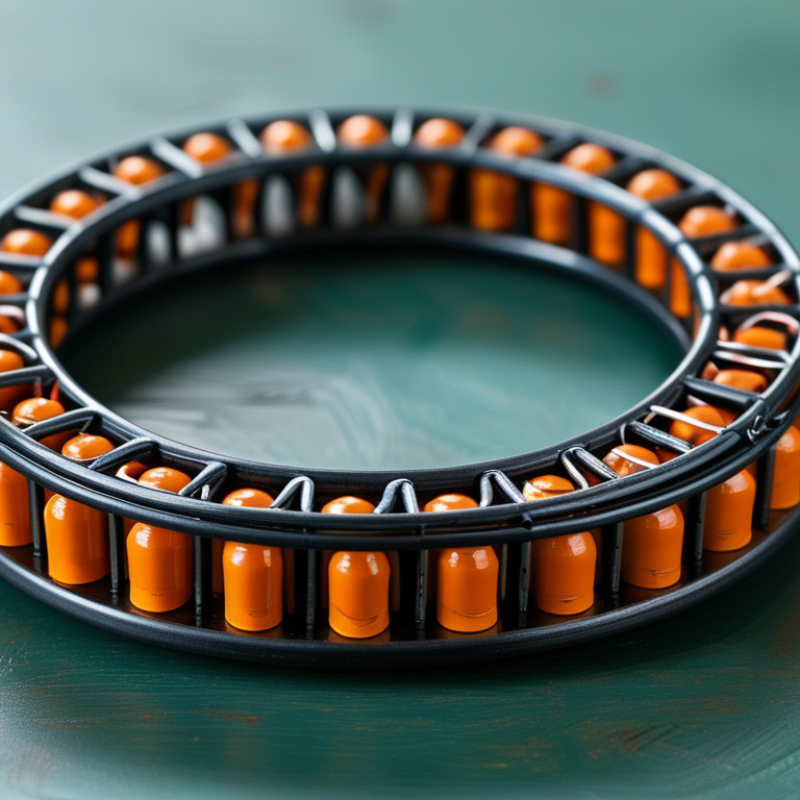
Definition and Basic Principles of Coil Inductors
A coil inductor is a passive electrical component that stores energy in a magnetic field. It consists of a wire wound into a coil shape. When current passes through the coil, it creates a magnetic field around it. This magnetic field can induce an electromotive force (EMF) when the current changes, which makes inductors crucial in many circuits.
The basic principle behind a coil inductor is electromagnetic induction, defined by Faraday's law. This law states that a changing magnetic field within a closed loop induces a voltage. According to industry reports, coil inductors are essential in applications like power supplies and filters. They help smooth out electrical signals and reduce noise. Data indicate that the global inductor market is expected to reach $2.5 billion by 2025, reflecting their importance in modern electronics.
Inductors are measured in henries (H), quantifying their ability to store energy. The design and material affect efficiency and performance. However, while inductor technology is advancing, challenges remain in miniaturization and efficiency at high frequencies. Finding the right balance between size and performance is an ongoing concern.
Types of Coil Inductors: Air-Core, Ferrite-Core, and Iron-Core
Coil inductors are vital components in many electrical circuits. They store energy in a magnetic field when electric current passes through them. The design of an inductor can greatly influence its performance. There are three primary types: air-core, ferrite-core, and iron-core inductors.
Air-core inductors are simple in construction. They consist of wire coils without a magnetic core. This design minimizes losses and provides high-frequency performance. However, they may suffer from saturation when too much current flows through, limiting their effectiveness in certain applications.
Ferrite-core inductors utilize ferrite material to enhance inductance and reduce losses. These inductors are excellent for high-frequency applications. Yet, using ferrite introduces the risk of core losses at higher power levels. Iron-core inductors, on the other hand, offer higher inductance values. They can handle significant currents, but their frequency response may be limited. Balancing the choice between these inductor types is crucial for optimal circuit performance. Each type has its strengths and weaknesses that should be considered carefully.
Inductance Calculations: The Role of Turns and Core Material
Inductance calculations are crucial for understanding coil inductors. These components store energy in a magnetic field when electric current passes through them. The number of turns in an inductor greatly impacts its inductance. More turns generate a stronger magnetic field, which enhances the inductance value. This relationship is fundamental in designing circuits that require specific inductive properties.
Core materials also play a significant role in determining inductance. Different materials can change how effectively the magnetic field is concentrated. Ferrite cores are common due to their high permeability. This makes them excellent for reducing losses at higher frequencies. However, choices like air as a core can result in lower inductance. It's essential to consider these factors when selecting materials.
Not all designs work out as intended, which is part of the learning process. Sometimes, the expected inductance does not match calculations. This discrepancy can stem from factors like core saturation or unexpected resistance. Testing and refining inductor designs is crucial for achieving desired performance in applications. Understanding these intricacies enhances your grasp of inductors and their roles in electronic circuits.
Inductance of Different Coil Inductors
This bar chart displays the inductance of various types of coil inductors measured in microhenries (µH). The inductance values vary based on the core material used in the coil construction, showcasing the importance of materials in determining the efficiency and performance of inductors.
Applications of Coil Inductors in Electronics and Electrical Systems
Coil inductors play an essential role in various electronic and electrical systems. They store energy in a magnetic field when electrical current passes through them. This property is vital in circuits where smooth current flow is necessary. They are widely used in power supplies, radio transmitters, and inductive heating applications.
These inductors can filter signals and handle high-frequency operations. In power supplies, they help regulate voltage and reduce noise. However, designing an efficient coil inductor requires careful consideration of wire type and winding techniques. An error in design can lead to inefficiency.
When working with coil inductors, remember that size matters. A larger inductor often means higher inductance but weighs more and takes up more space. On the other hand, smaller inductors help save space but may not handle high currents well. Balance is crucial.
Understanding their limitations can improve design choices. For instance, overheating is a concern in high-performance applications. Ensure your inductor's thermal management is adequate. It prevents failures and ensures reliability in your systems. Inductors are versatile, yet they come with challenges that must be addressed for optimal performance.
Impact of Frequency and Resistance on Inductor Behavior and Efficiency
Inductors are crucial components in electronic circuits. Their performance largely depends on frequency and resistance. Higher frequencies can lead to increased losses in inductors. When the frequency rises, the skin effect comes into play. This phenomenon causes the current to concentrate on the surface of the conductor. As a result, the effective resistance increases. Reports indicate that at frequencies above 1 MHz, inductive losses can reach up to 30% in poorly designed coils.
Resistance also plays a key role in inductor efficiency. Ohmic losses, or copper losses, occur due to the inherent resistance in the wire. Higher resistance means more energy dissipated as heat. Studies show that a 20% increase in wire resistance can reduce inductor efficiency by approximately 15%. It's essential for designers to balance the wire gauge and the number of turns to minimize these losses.
In some scenarios, optimizing for lower resistance may lead to mechanical stability issues. Coiling wire tightly can result in manufacturing difficulties and higher production costs. Furthermore, selecting inappropriate materials can compromise performance. These reflections highlight the complexity in designing efficient inductors. Balancing frequency and resistance is not straightforward and requires careful consideration.
What is a Coil Inductor and How Does it Work? - Impact of Frequency and Resistance on Inductor Behavior and Efficiency
| Inductor Type | Inductance (H) | Frequency (kHz) | Resistance (Ω) | Efficiency (%) |
| Air Core Inductor | 10 μH | 100 | 0.1 | 95 |
| Ferrite Core Inductor | 22 μH | 150 | 0.3 | 92 |
| Toroidal Inductor | 47 μH | 200 | 0.2 | 90 |
| Choke Inductor | 33 μH | 50 | 0.4 | 88 |
| Variable Inductor | 15 μH | 75 | 0.5 | 85 |